 Polski
 Русский
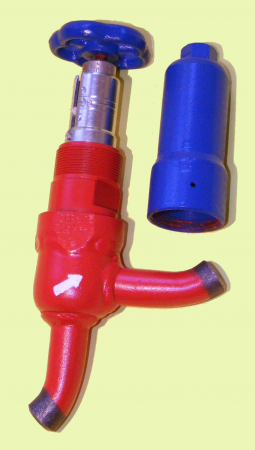
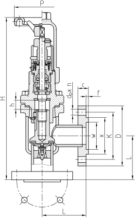
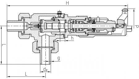
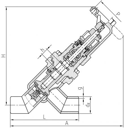
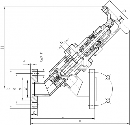
Regulating valves can be either throughway or angle valves, bolt and with or without flanges. Flangeless valves are equipped with connector pipes with dimensions in accordance with PN-80/H-74219 norm and with DIN 2448 standard (marked additionally with symbol: /D). Differences in dimensions are showed in the tables. All regulating valves have an unslidable spindle. Valves’ leaktightness in closure position is secured by P.T.F.E. gasket pressed down by the valve head. The casing is made from welded high resistance P355 steel. When the valve is fully open (by turning the handwheel left as far as possible), the inflow of the medium to the stuffing box is cut off, which makes it possible to replace the spindle gasket in a valve that is under pressure. If frequent opening and closing of the valve is not required, semi-hermetic valves with a cap cen be installed, in which the cap covers tightly the upper part of the spindle and the gland seal. After reversing the cap, it can be used as a handwheel.
Flow regulating valve
ZR

Flow regulating valve
ZRKb
Flow regulating valve
ZRKk
Flow regulating valve
ZRKs
Flow regulating valve
ZRPb
Flow regulating valve
ZRPk

Flow regulating valve
ZRPs
Working parameters for ZRPb 10-80, ZRKb 10-80:
working pressure: 25 bar, temperature range: – 40ºC / +150ºC.
Working parameters for ZRPk 10-80, ZRKk 10-80:
working pressure: 25 bar, temperature range: – 40ºC / +150ºC.
Working parameters for ZRPs 10-20, ZRKs 10-20:
working pressure: 25 bar, temperature range: – 40ºC / +150ºC.
Working medium: refrigerants.